Exploring embedded programming with the Sipeed M0S with the BL616 microprocessor
Note: I do not use Amazon affiliate links. The Amazon links below do NOT kick anything back to me.
This is part of an ongoing series:
- Part 1: Exploring embedded programming with the Sipeed M0S with the BL616 microprocessor
- Part 2: Getting to hello world with Sipeed m0s (BL616)
- Part 3: Simplifying our tool chain: First steps
- Part 4: Simplifying the tool chain: Wrap up
- Part 5: Learning the SDK and USB protocol
- Part 6: Wrapping up our exploration: A mini shell
I have been dabbling in low level programming lately. Late last year, I put together a Hello World assembly language sample in multiple ISAs to see the difference between various CPU architectures. To create something a bit more realistic, this included the use of Linux syscalls, so these samples work but require Linux. The advantage here is that I was able to understand better how programs actually interface with the OS (as long as the OS is Linux :) ). This repository is here: https://github.com/elerch/assembly-samples
I also created a zig-based program to interface with a small OLED display I got for Christmas. This was pretty fun, and allowed me to use some new features in the newest unreleased version of zig to automatically download/build ImageMagick and compile it into a single static binary that can work with these devices. There’s lots more that can go into this program, but the exercise really was about getting closer to the hardware/software interface. It has literally been decades since I’ve had to cross reference data sheets with my code and worry about things like clock dividers, etc.
Most recently, I read the book Code, which reminded me a lot about my undergrad classes at Lehigh, and refreshed my memory on how hardware/firmware/software interact. Indeed, it went beyond some of the classes I had had, and overall it was a very pleasant read. Highly recommended book, although it gets pretty dense, so if you’re not super into this stuff, you might want to read until your eyes glaze over, then skip to the last three chapters or so where things get a bit higher level again.
Some of the trigger for this is my recent interest in Risc-V. I’m pretty excited overall for this instruction set architecture (ISA). Wikipedia has many more details, but this is an ISA that was developed at University of California, Bekeley to be an open source ISA. The ISA describes the interface between software and hardware for CPUs. So now there is an open standard interface, and hardware designers can create either open or proprietary CPU designs that adhere to that interface. An open ISA frees developers from specific vendors that may have business issues or come under political pressure. Because of this, RISC-V is already wildly successful, though only in the embedded world. That said, the possibility of RISC-V phones, tablets, and computers are on the horizon.
With this interest, I have been experimenting with real hardware. My first experiment was using Debian on the Sipeed LicheeRV Dock and shortly thereafter on the MangoPi MQ Pro. These are both based on the Allwinner D1, and are therefore nearly identical. This was an exciting but also somewhat disappointing step. Exciting because wow, Linux on RISC-V hardware in my house that wasn’t crazy expensive, but disappointing as I found the performance to be somewhere between the Raspberry Pi Zero and the Raspberry Pi Zero 2. Ultimately, I didn’t do a lot with it.
Next up, is the much more exciting StarFive VisionFive 2. With super early bird discount, I ordered the 8GB version for less than $100 and was able to get Debian up and running. Now, this is still very early days, requiring firmware updates, custom linux kernels and the use of a USB to TTL console cable (Raspberry Pi directions here: https://learn.adafruit.com/adafruits-raspberry-pi-lesson-5-using-a-console-cable).
But…it was up and running, and the performance was much better, clocking in somewhere between a Raspberry Pi 3 and a Raspberry Pi 4. If we think about this, the industry, in a matter of less than a year, brought Linux RISC-V performance up basically 1.5 generations of Raspberry technology. Looking to the future, in a few days from my writing of this we are expecting Sipeed to allow orders of the Lichee Pi 4A, which promises performance slightly above the Raspberry Pi 4, still within a year timeframe from the LicheeRV.
Embedded programming
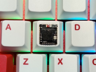
So far, I’ve only briefly mentioned embedded. Well, based on my excitement of RISC-V and my close following of Sipeed in particular, I saw an announcement of the ability to run Linux on a tiny MCU. The Sipeed M0S is the successor to the announcement above, is also able to run Linux, and is really, really tiny. Here’s a couple photos, first of the chip:
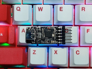
Then of the chip attached to the dock for development:
Keep in mind…this thing was $4, and can run Linux! Not very well I’m sure, but it’s possible. So, I wanted to play around with it, get down to metal, because considering it is the size of my fingernail, this thing is a beast.
This has sent me (back) into the world of super-low level programming, which I had done a long time ago before the Internet really took off. So far, I’m having fun rediscovering this world, but been running into a lot of “hey, we assume you already know ”, or documentation not in my native language, so I’m documenting my journey here.
Getting started
Pulling this thing out of the box, we have some IO pins, chip, and power/data
in the form of a USB-C port. Cool…let’s plug it in. I’m running Linux on my
desktop, so I issue sudo dmesg -w when I plug it in to watch what the system
does with this thing. I’m presented with:
[8691832.938863] usb 1-10.3: new high-speed USB device number 54 using xhci_hcd
[8691833.063072] usb 1-10.3: config 1 interface 0 altsetting 0 endpoint 0x83 has an invalid bInterval 0, changing to 7
[8691833.063255] usb 1-10.3: New USB device found, idVendor=349b, idProduct=6160, bcdDevice= 2.00
[8691833.063257] usb 1-10.3: New USB device strings: Mfr=1, Product=2, SerialNumber=0
[8691833.063258] usb 1-10.3: Product: Bouffalo CDC DEMO
[8691833.063259] usb 1-10.3: Manufacturer: Bouffalo
[8691833.066752] cdc_acm 1-10.3:1.0: ttyACM0: USB ACM device
ok, cool. Linux seems happy with this. What the heck is a USB ACM device? I’m
used to something like /dev/ttyUSB0 or something, but not this. A couple
searches later, I find this means “Abstract Control Model”, and was used for
communication devices back in the day, but is common for MCU programming in 2023.
More information can be found here: https://rfc1149.net/blog/2013/03/05/what-is-the-difference-between-devttyusbx-and-devttyacmx/
Now I need to figure out how to flash it, so I pull the BouffaloLab SDK. Later, I found that there is a fork of this repo specific to the M0S. So, we’ll put investigation of the differences here on the to do list, but at a quick glance it looks like these two repos have their first common ancestor on March 9th in 9b5177d.
ok, next to build and run. This…gets tricky as I get a lot of documentation in a language different from my native language, and I’m also not used to this low level work. I keep seeing references to binary blobs checked into repos, and it looks like this is mainly a complaint focused on the actual flashing software. But let’s get the code built first.
For Linux, the environment setup refers to using this pre-built toolchain. I am not a huge fan of this, but we’ll go with it for now and add another item on our to do list to revisit later. I sure as heck am not going to just run this directly on my host, even though it theoretically is built from source much like this. Ultimately I would love to just build with Zig and take advantage of the cross platform capabilities, but again, let’s just get something running.
Docker is my typical tool of choice here, though when I run docker I always run my docker with podman. Daemonless is nice, but it’s also using uid mapping, so I can just run as root inside the container, and files I touch as root there are actually my usual user on the host. It helps with a lot of permissions shenanigans. So with the SDK and the toolchain cloned in sibling directories, and with my current directory the SDK, I startup a container:
podman run --rm -it -v ${PWD}:/build -v ${PWD}/../toolchain_gcc_t-head_linux/:/toolchain --device /dev/ttyACM0 debian:bullseye
Note I’ve passed my device over to the container, although ultimately, I won’t
end up flashing from within the container. I’m using debian:bullseye because
I’m mostly familiar with debian, that’s what I run on my host, and most SDKs
assume you use Ubuntu, which is based on debian and usually close enough for
things to work. If you’re following along at home, note the use of --rm
means the container will disappear as soon as you leave it, so be careful.
Eventually, I find the following commands within the container work wonderfully:
apt update && apt install -y build-essential
export PATH=/toolchain/bin/:$PATH
cd build/examples/helloworld/
make CHIP=bl616 BOARD=bl616dk
make flash CHIP=bl616 COMX=/dev/ttyACM0
The whole COMX thing tripped me up a bit. First, it’s Windows terminology.
Second, what’s with the X? The make commands invoke CMake, and when I screwed
up the make commands I often had to delete the build directory inside the
helloworld directory.
We’re built! Now to get this the code onto the device. After some trial and error, I find the following procedure to work:
- Hold down the
bootbutton - Plug into USB
- Release the
bootbutton - Run
make flash CHIP=bl616 COMX=/dev/ttyACM0from the host while inside examples/helloworld in the SDK
After doing this, you can unplug/plug in the device, and magically it’ll work!
Umm..no, of course not. The first time I did this, I noticed that after plugging
it back in, my /dev/ttyACM0 is totally gone. My theory is when the device is
shipped, it’s shipped with firmware that allows you to upload firmware without
pressing the boot button on power on. To get /dev/ttyACM0 back, you need to
hold down the boot button while plugging it in. Then you can release the button.
I believe that the boot button simply toggles which firmware is run at startup. With the boot button we get the “firmware loading firmware”, and without, we get “whatever I compiled and uploaded” firmware to run. The helloworld firmware just prints out “hello world” somewhere. It’s our job to find out where. And Linux isn’t showing anything. Being impatient, I don’t have time for any of this detective work at the moment. So, to do list item #3, and let’s see if we can do the universal Internet of Things version of hello world, otherwise known as “get to blinky”.
So, a few short searches later, I stumble on this gist (thanks some random Internet person!). So, I give a quick glance at the code, it looks reasonable, and I build/flash it to the device. Success! I now have two LEDs built into the dev board alternating every 500ms. Current todo list:
- What’s the difference between Bouffalo Labs’ SDK and Sipeed’s repo?
- Avoid binary toolchains
- Figure out what’s up with hello world
We’ll take these in order, so first up:
Figure out what’s up with hello world
Hello world is going to be outputting somewhere. That’s kind of it’s entire purpose in life, after all. There are two reasonable places (maybe a third?) it could output, and my assumption going into the world of “hello world” was that it would be the first. However, that’s clearly not correct:
/dev/ttyACM0- The serial console
- (??) JTag. I don’t know too much about JTag, so if it’s that, we have another item for the todo list
If you recall, on flashing the example, my ACM device disappeared. So, we could be at the serial console. Where is that exactly? Time for some digging. We’ll need the following for our detective work.
Because the hello world example is using a bunch of logging statements, I do
have some concerns it might be outputting to JTag. So let’s find a different
example that’s definitely not using that. Shell looks fun! So we’ll go into
examples/shell and see what’s there. There’s an OS and a non-OS version, but
we want to remove abstractions and learn this ground up, so we’ll go with
non-OS.
Let’s flash it for fun and see what we get. Well, nothing. It’s the same as
hello world. No device in /dev for screen or anything to attach to. But this
one is much more likely to be intended for use on a serial console. Looking at
the source code, we find it’s clearly trying to use uart0:
int main(void)
{
    int ch;
    board_init();
    uart0 = bflb_device_get_by_name("uart0");
Cool. But we need to know where uart0 physically is so we can connect to it.
Right now, I assume it’ll be one of the I/O pins we see hanging off the end of
the dock. grep -r board_init from the base of the SDK brings up too much noise,
but doing another grep -r uart0 yields a few interesting bits. Specifically,
There is a drivers/lhal/config/bl616/device_table.c file that looks interesting.
Looking at that file ultimately doesn’t give me too much…but let’s put a pin
in that one because it may come in handy later. What looks really interesting
is bsp/board/bl616dk/board.c, so let’s take a peek there. A few searches through
that file looking for uart0, and pay dirt:
static void console_init()
{
    struct bflb_device_s *gpio;

    gpio = bflb_device_get_by_name("gpio");
    bflb_gpio_uart_init(gpio, GPIO_PIN_21, GPIO_UART_FUNC_UART0_TX);
    bflb_gpio_uart_init(gpio, GPIO_PIN_22, GPIO_UART_FUNC_UART0_RX);

    struct bflb_uart_config_s cfg;
    cfg.baudrate = 2000000;
    cfg.data_bits = UART_DATA_BITS_8;
    cfg.stop_bits = UART_STOP_BITS_1;
    cfg.parity = UART_PARITY_NONE;
    cfg.flow_ctrl = 0;
    cfg.tx_fifo_threshold = 7;
    cfg.rx_fifo_threshold = 7;

    uart0 = bflb_device_get_by_name("uart0");

    bflb_uart_init(uart0, &cfg);
    bflb_uart_set_console(uart0);
}
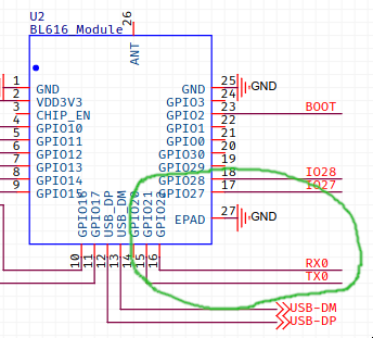
ok - so UART transmit is on GPIO pin 21, and receive is on pin 22. We also have uart speed, parity, data bits, flow control. Everything we could ever want. But where is GPIO pin 21 and 22? Let’s take a look at some schematics. There are two sets of schematics. Ultimately we’re looking for where to plug a TTL to USB device into the DOCK, so we’ll want to look at the dock schematic from the link above. Doing so, we can find GPIO21 and GPIO22 sitting in the bottom right of the schematic where it pictures the BL616 module.
Next, we have to find out where RX0 and TX0 go. Looks like that…is right here:
So we’re looking for J4. It’s not clear from the schematic or the data sheet where J4 is, but J4 has TX, RX and a Ground, so three holes. The board is pretty tiny, so it’s not a lot of real estate to search. The answer seems to be “right next to the USB plug”. I don’t really want to pull out a soldering iron in this process, so I have three questions at this point:
- Can I just stick wires into these holes in the board?
- Can I move to other GPIO pins?
- Can I route communications directly through the USB port I’m already plugged into?
The third option seems especially relevant given I started this journey with
a /dev/ttyACM0 device. 2,617 words later though, let’s visit this in another
post.


